
What Is a Continuity Test?
A continuity test is an electrical check that shows whether a complete path exists between two points in a circuit. A meter sends a small test signal through the selected path and detects low resistance when the path is intact. A high reading indicates an open connection, damaged conductor, switch, fuse, or component.
Quick Facts About Continuity Test
Category
Electrical diagnostic test
Used for
Finding open or interrupted paths
Common confusion
Continuity is not the same as voltage
Typical tool
Multimeter
Also called
Continuity Check, Circuit continuity test
Often discussed with
Electrical Troubleshooting
Key Takeaways About Continuity Test
- Continuity checks a path, not the circuit’s operating voltage.
- A low-resistance reading usually indicates a complete path.
- Continuity does not prove that a circuit can carry its intended load.
How Continuity Test Works
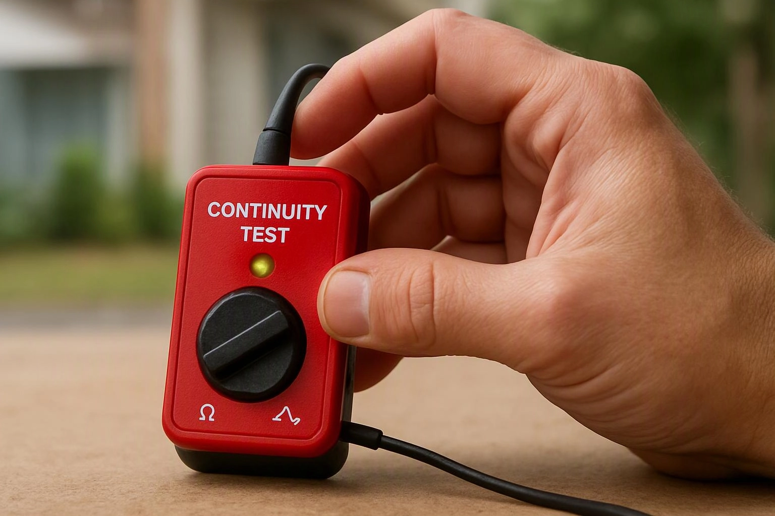
Continuity test checks the electrical path between selected points. A multimeter applies a small test signal and measures resistance through the path. Low resistance indicates that the path is complete, while a high reading indicates an open path. Some meters provide an audible tone for a complete path.
Related glossary terms: Electrical Meter, Ohm, Voltage Tester.
Technicians compare the reading with the circuit’s design and the component under test. A switch may show continuity in one position and an open path in another. A fuse should provide a continuous path when intact. The test can also help trace a broken conductor or a loose termination.
Continuity testing does not measure normal operating voltage or prove that a circuit can carry its intended load. Electrical meters often combine continuity testing with resistance and voltage functions. The selected function must match the diagnostic task.
From the Chris Miller Electric team
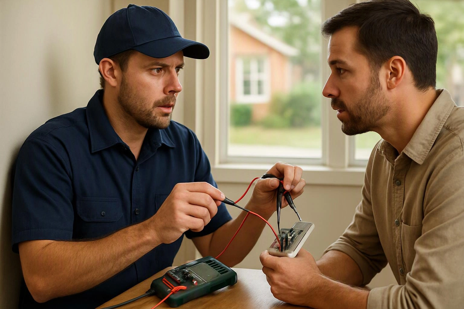
When we troubleshoot a circuit, we use continuity testing to trace suspected breaks and verify accessible connections. We interpret the reading alongside the circuit layout and component function. A passing result does not end the diagnosis, because a path can remain continuous while another fault affects circuit operation.
Continuity Test in Practice: A Real-World Example
A homeowner reports that a light switch does not control a fixture. During electrical troubleshooting, we use a continuity test to check the switch and the related conductor path for an open connection.
Related Services
Related Terms
Electrical Meter
An electrical meter is a testing instrument that measures electrical values in a circuit, such as…
Ohm
Ohm is the standard unit of electrical resistance. Resistance describes how strongly a material or component…
Voltage Tester
Voltage Tester is a handheld electrical testing tool that indicates whether voltage is present in a…
Wire Nut
Wire Nut is a twist-on connector that joins electrical conductors inside a junction box or enclosure…
Chris Miller Electric
Have Questions About Continuity Test?
Contact Chris Miller Electric for practical guidance on Continuity Test and related 24 hour electrician work in Fort Wayne.